Overview
This project began as a proposal-support request for one comparison figure and expanded into a full aerospike thermal and performance trade study. The objective was to quantify whether aerospike integration could improve flight performance while remaining feasible under predicted thermal loads.
Artifact classification
- Category: Academic artifact (CFD proposal project)
- Related HIE: BEFAST Lab Research
Problem Statement
At high Mach conditions, aerodynamic gains from an aerospike can be offset by severe thermal loading and integration complexity. The project needed to answer three practical questions:
- What heat flux and heat-load levels are expected across candidate geometries?
- Which material choices are realistic for those thermal demands?
- Do external performance gains justify integration tradeoffs?
Methods and Tools
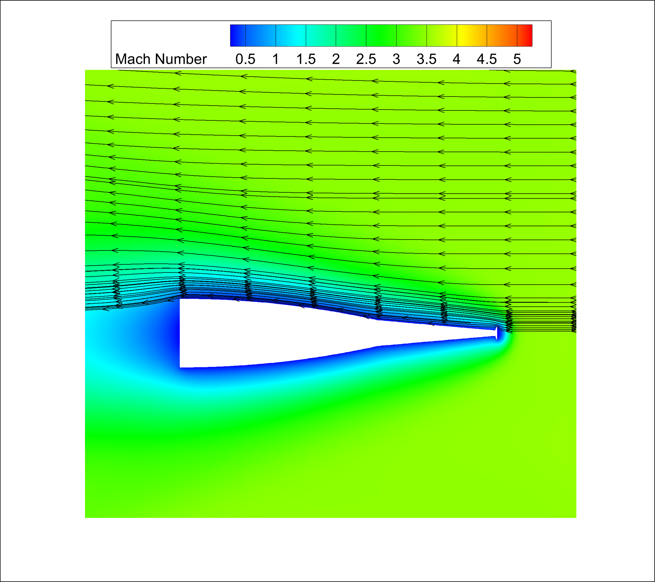
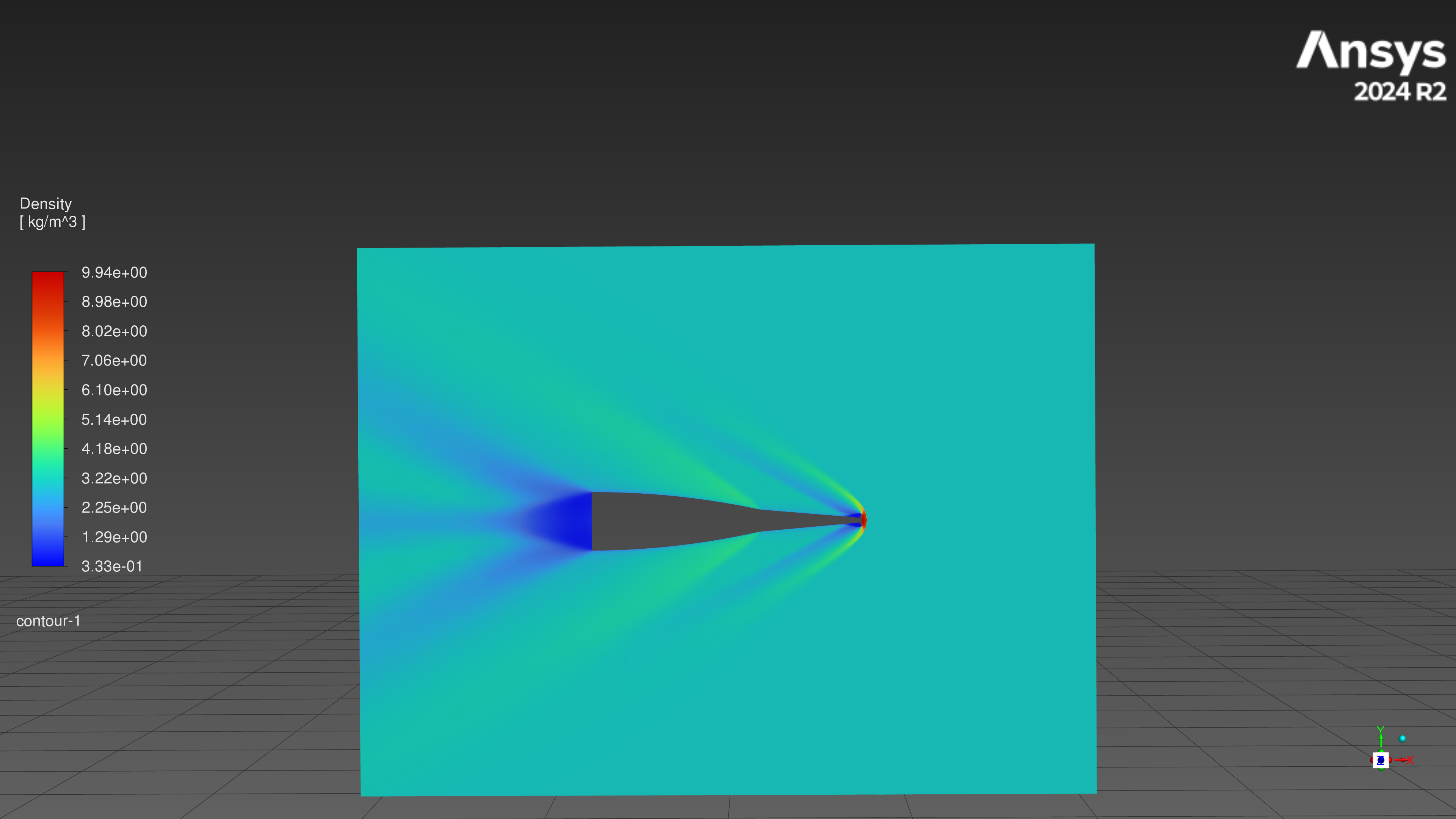
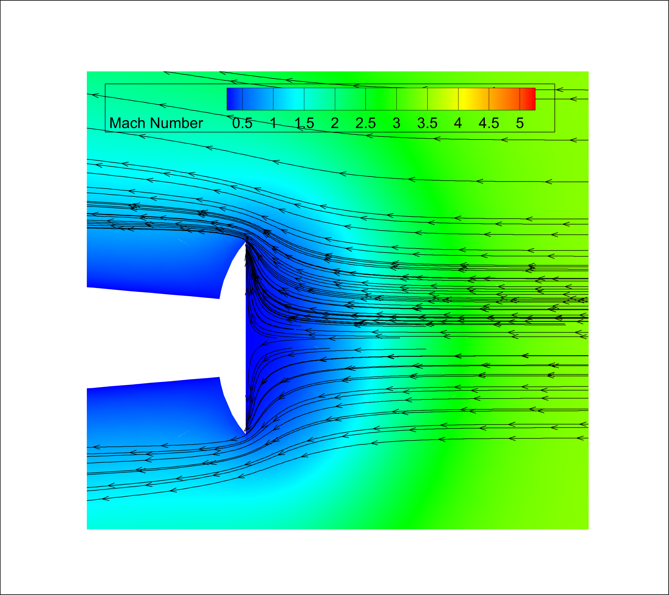
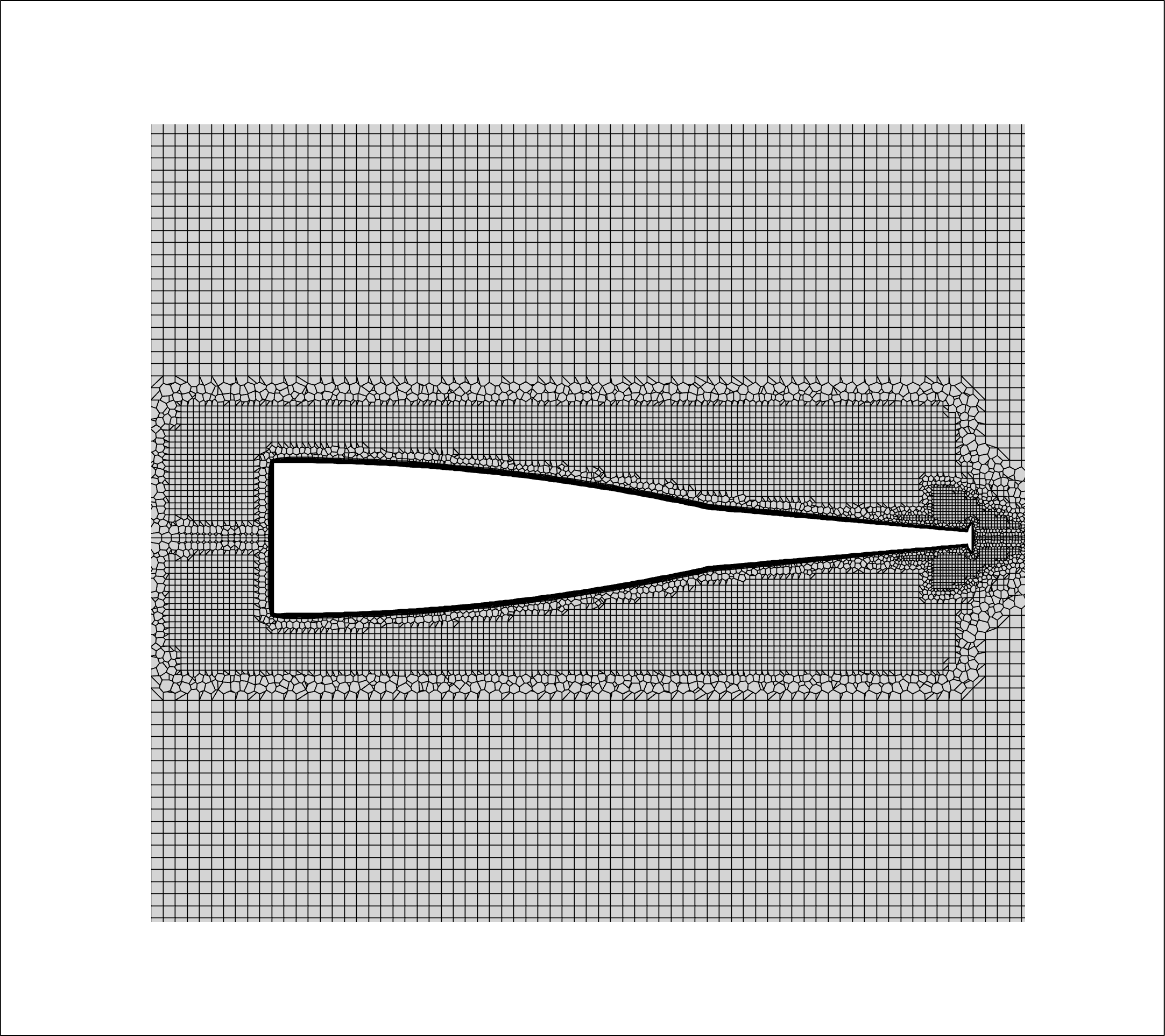
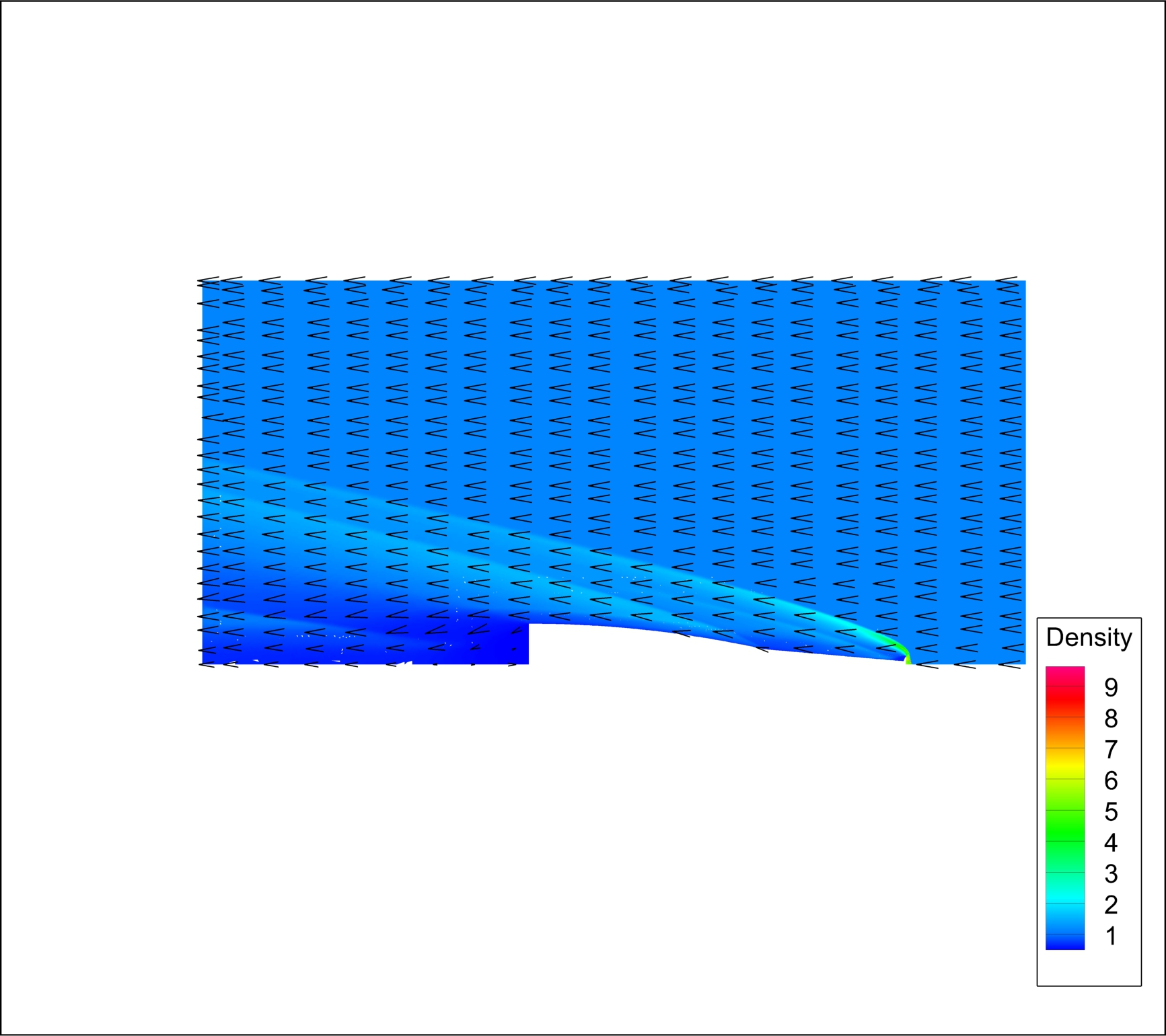
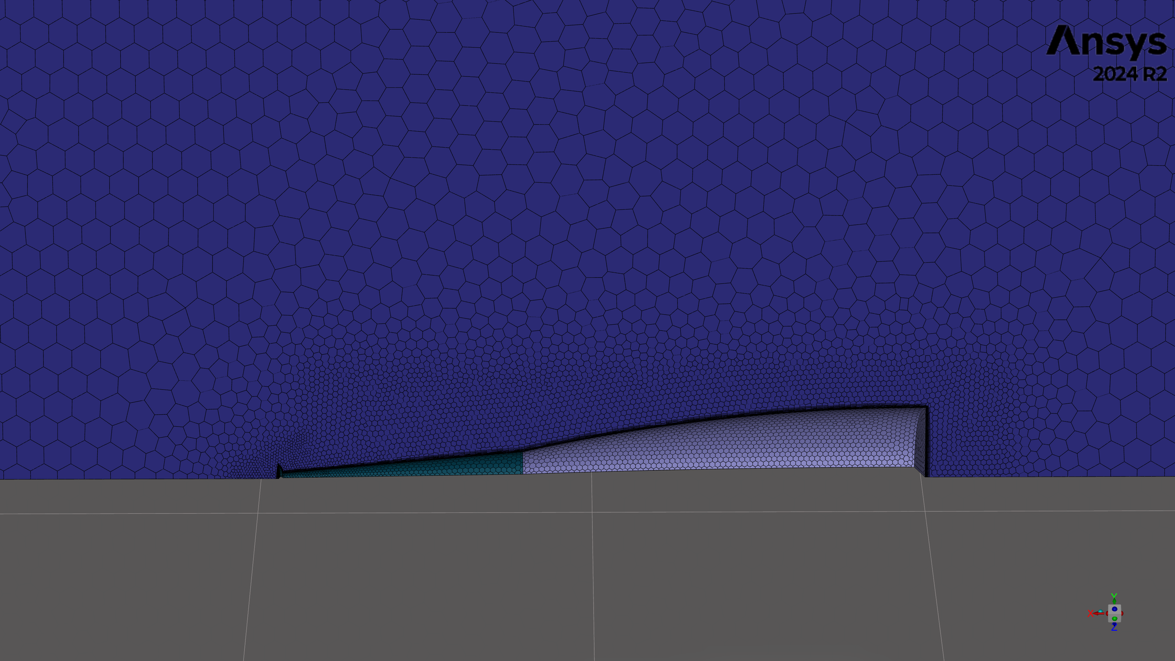
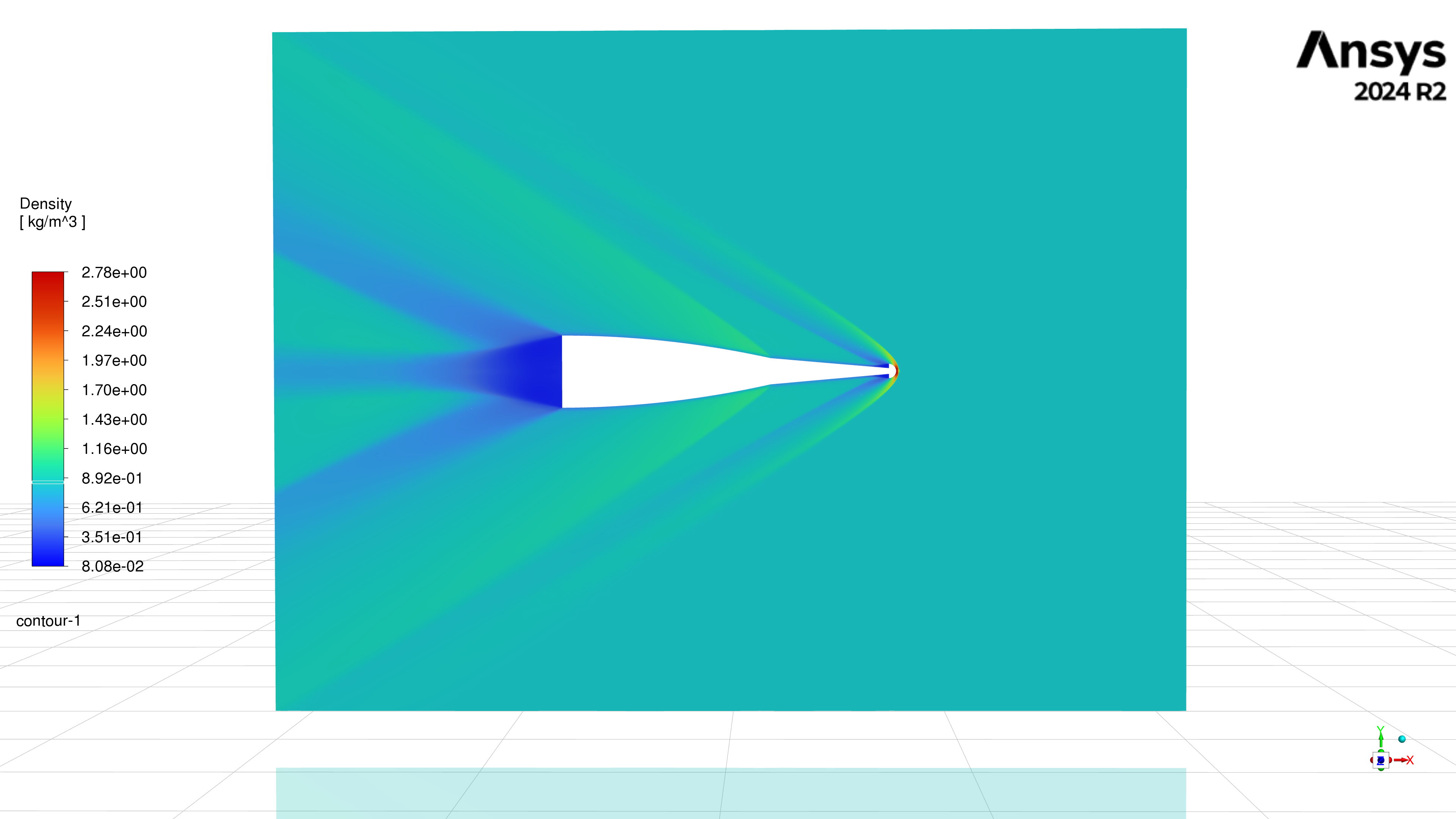
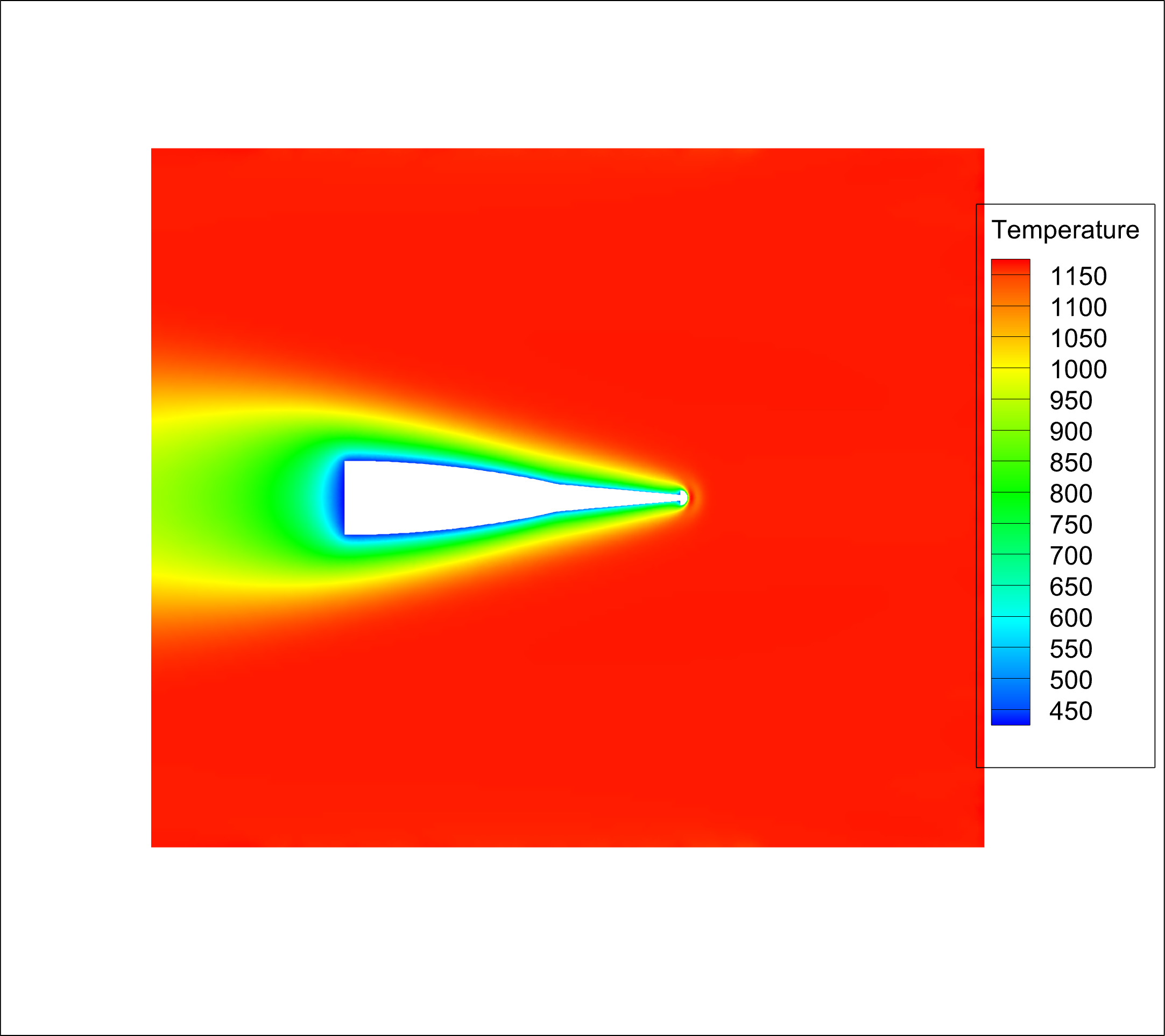
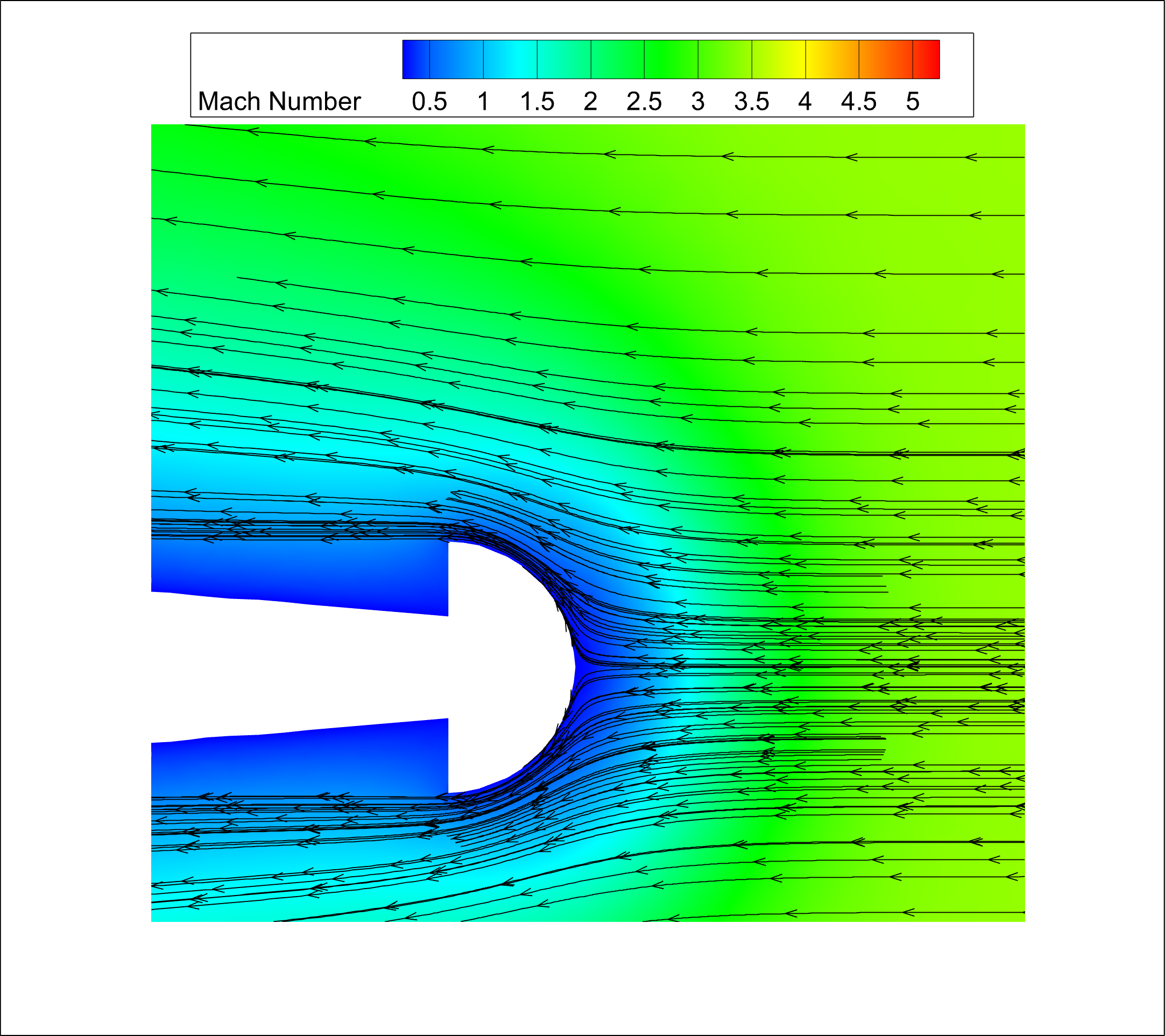
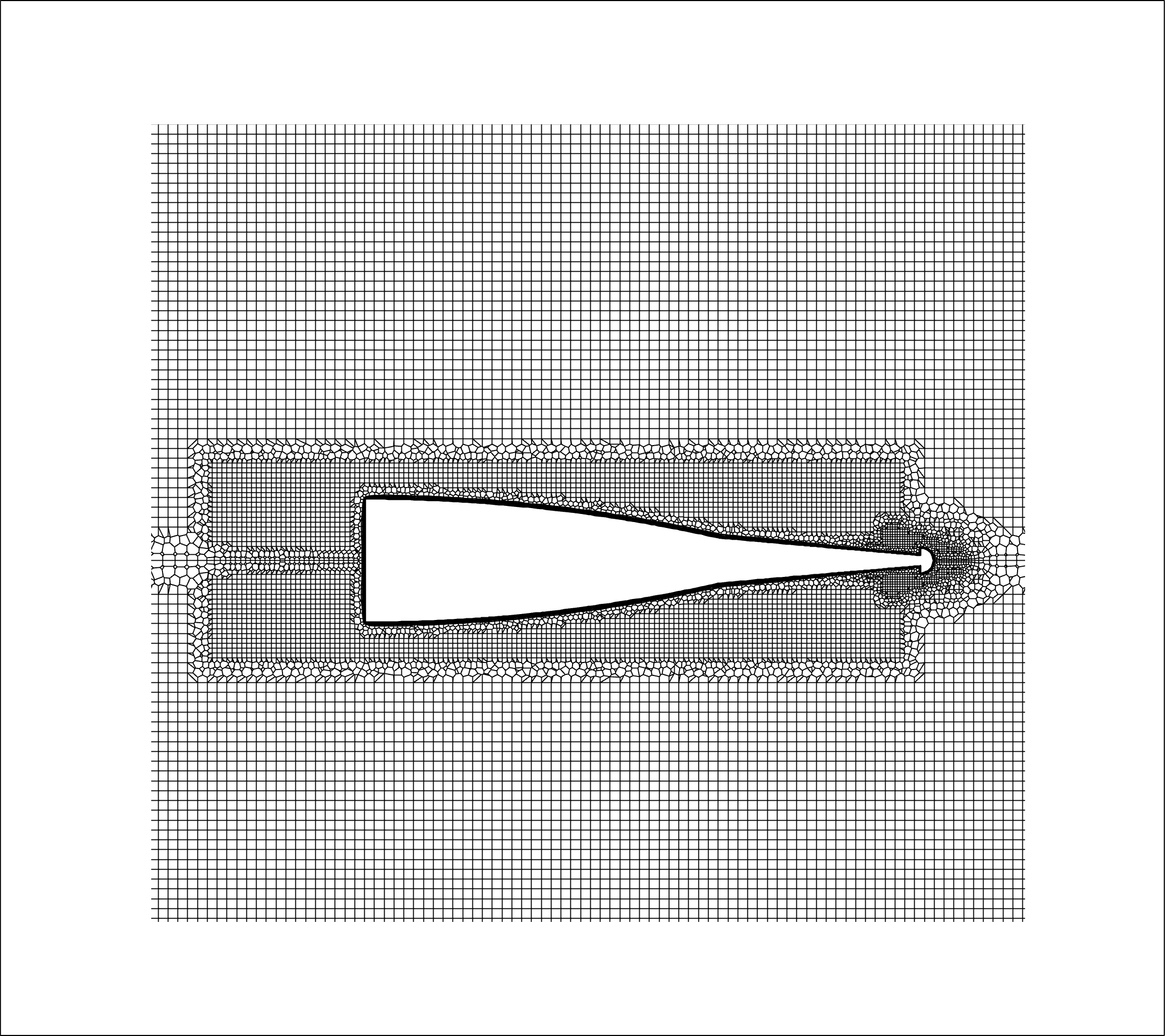
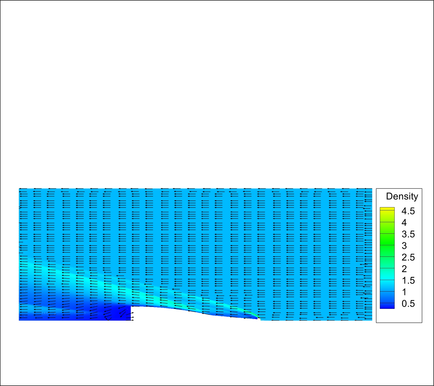
- CFD: ANSYS Fluent simulations across Mach 3 to Mach 5 for multiple aerospike geometries
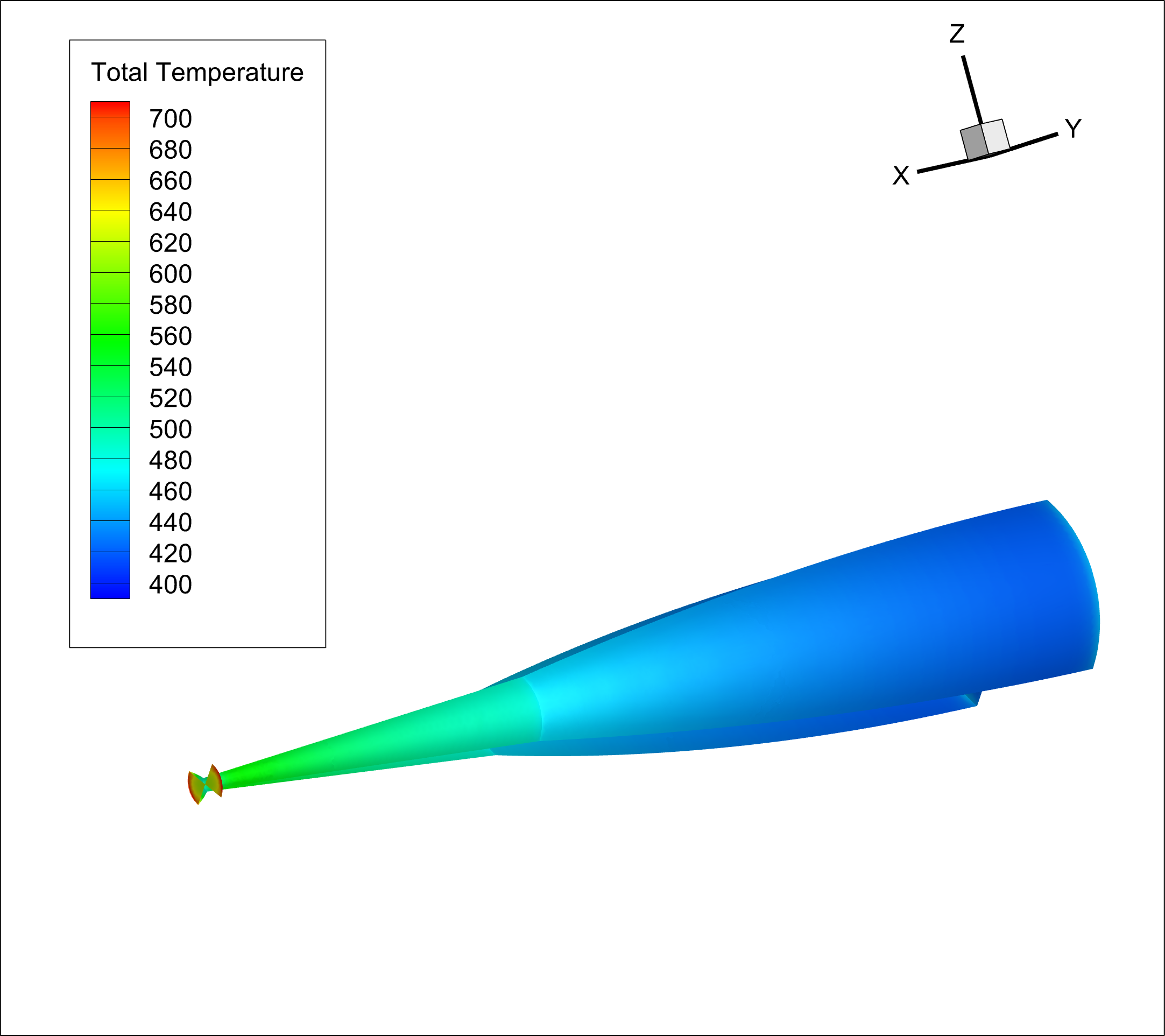
- Thermal analysis: local heat-flux and total heat-load evaluation across geometry variants
- External performance checks: OpenRocket modeling for drag and apogee trend impact
- Mechanical integration concept: SolidWorks design for a deployable nose-cone aerospike assembly
Key Results
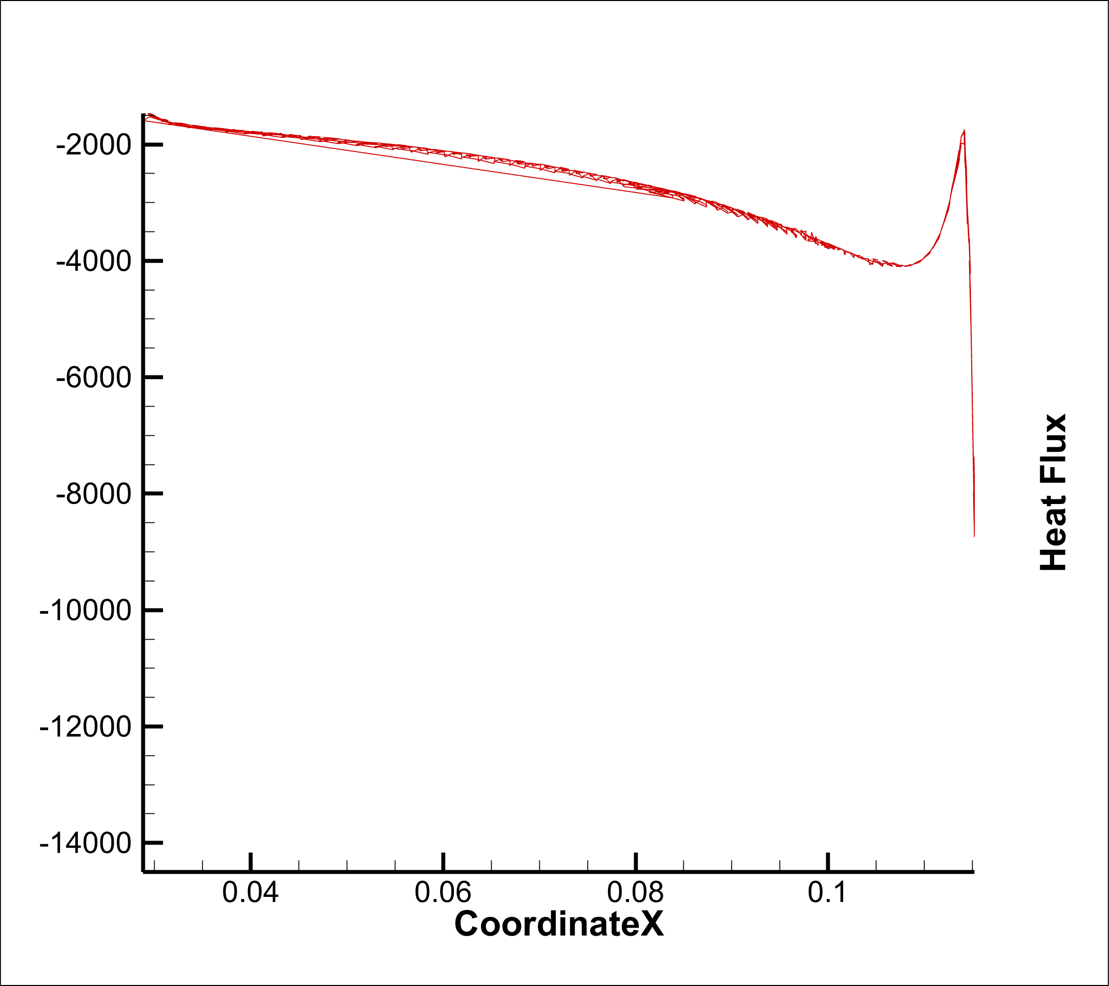
- Peak heat-flux values were on the order of roughly 3 to 5 MW depending on condition and geometry
- Material recommendation converged on hot-pressed silicon nitride for thermal resistance considerations
- OpenRocket trend results suggested about 3% to 5% drag reduction and near 10% apogee gain in modeled cases
- The final concept moved beyond simulation-only evidence by linking thermal results to a feasible deployment concept
Engineering Trade Study Insight
The project framed aerospike adoption as a coupled thermal-structural-performance decision, not a pure drag optimization. Thermal survivability and added mass implications must be evaluated together with aerodynamic benefits to produce credible design recommendations.
My Contribution
- Led simulation setup and thermal post-processing workflow
- Interpreted model outputs into actionable design implications
- Proposed material pathway aligned to heat-load conditions
- Connected CFD findings to system-level integration and performance discussion
CFD Contour Slideshow
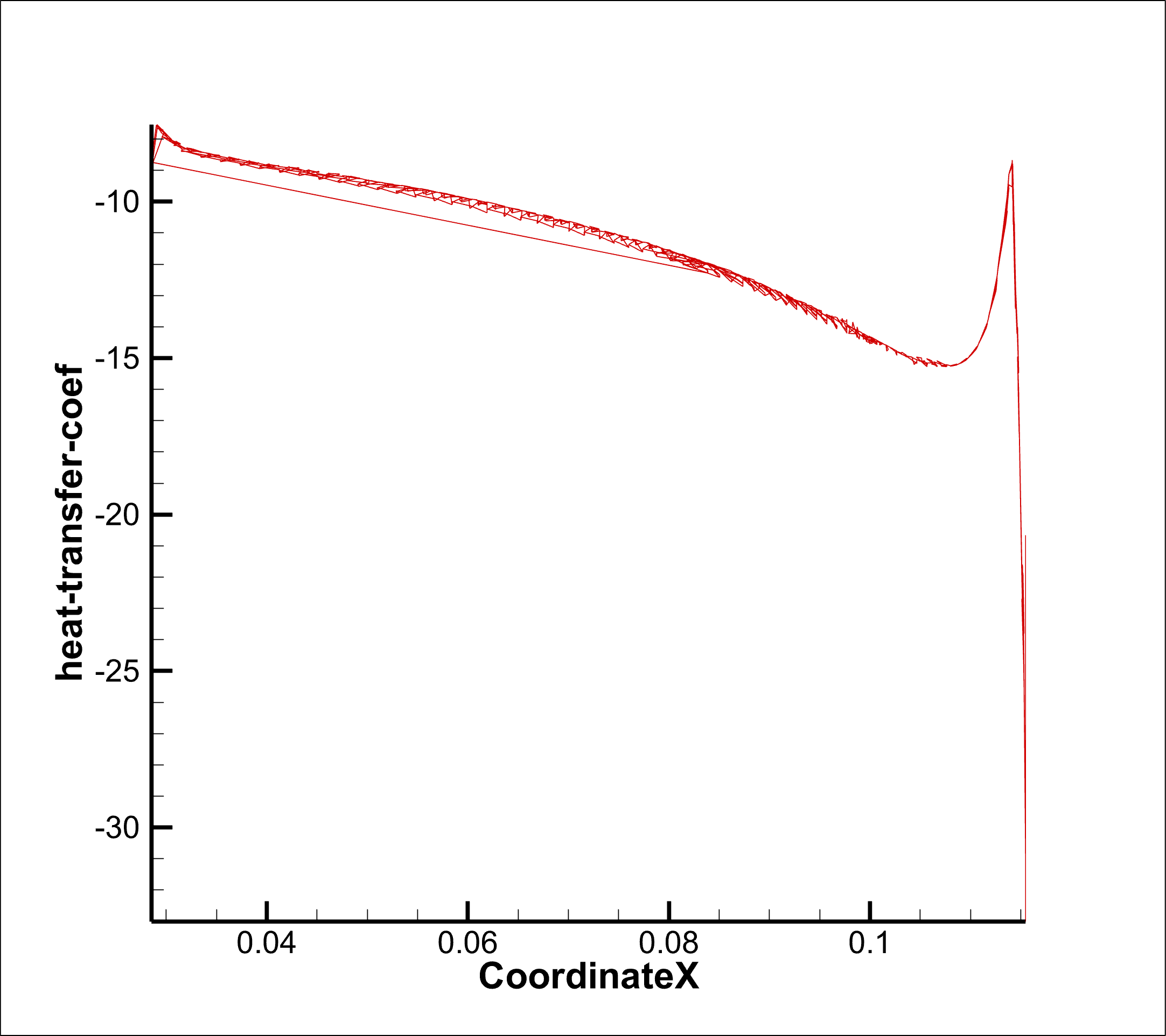
CFD Graphs Slideshow
Reflective Caption
In this CFD proposal project, I evaluated aerospike geometries under Mach 3 to Mach 5 conditions to quantify both thermal risk and aerodynamic benefit. I translated simulation evidence into practical decisions about materials and deployable integration, rather than stopping at isolated contour plots. This artifact reflects growth in analytical rigor, system-level thinking, and engineering communication.